
CO₂ Capture and Carbon Management
Next-Generation Modular Solutions for Industrial Emissions
ERGIL | Äager GmbH — Engineering, Manufacturing & Modular Process Solutions
Industrial decarbonization cannot rely on fuel switching and efficiency alone. In sectors such as cement, steel, refining, chemicals, and hydrogen production, a substantial share of CO₂ is generated by the process itself. Carbon Capture, Utilization and Storage (CCUS) provides a practical route to separate this CO₂ before it reaches the atmosphere — and modular, skid-mounted capture systems are making the technology accessible to a far wider range of facilities. This article explains where industrial CO₂ comes from, how capture systems work, which technologies are available, and how ERGIL’s modular pilot platform translates this into deployable, scalable solutions.
CO₂ Emissions and Their Sources
Rising energy demand, industrialization, and the continued intensive use of fossil fuels have driven atmospheric greenhouse gas concentrations steadily upward. Among these gases, carbon dioxide (CO₂) is the most significant component of emissions from human activity: global atmospheric CO₂ concentrations exceeded 428 ppm in 2026 — roughly 50% above pre-industrial levels.
A large share of CO₂ emissions originates from energy generation and fuel consumption. In several industries, however, CO₂ is generated directly by the production process itself, which means it cannot be eliminated through energy efficiency improvements or fuel switching alone. Examples include limestone calcination in cement production, reforming for hydrogen production, natural gas processing, refinery operations, iron and steel making, and various chemical production routes.
The main point sources of industrial CO₂ emissions are:
- Power and heat generation: Combustion of coal, natural gas, and other fossil fuels for electricity and steam.
- Refining and petrochemicals: Process furnaces, fuel gas combustion, and hydrogen production units.
- Cement and lime production: Process emissions from calcination reactions in addition to fuel combustion.
- Iron and steel production: Emissions associated with fuel consumption and reduction processes.
- Chemical production: CO₂ released during the production of hydrogen, ammonia, methanol, and other chemicals.
- Natural gas processing: CO₂ separated from natural gas streams and emissions from process operations.
Not all sources are equal from a capture perspective. Streams with higher CO₂ concentrations, arriving from a defined point at stable conditions, provide more favourable economics for capture systems. Accurately characterizing the emission source is therefore the first — and one of the most important — steps in any carbon capture project.
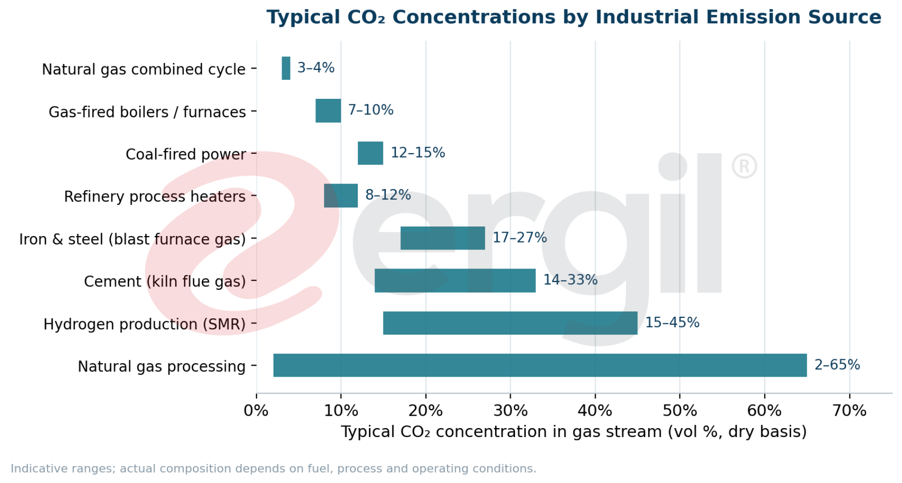
Figure 1. Typical CO₂ concentration ranges by industrial emission source. Higher concentrations generally reduce the specific cost and energy demand of capture.
Why Is CO₂ Capture Needed?
Several approaches are being pursued to reduce carbon emissions from industrial facilities: energy efficiency improvements, electrification, renewable energy, and the transition to lower-carbon fuels. Yet in sectors such as cement, iron and steel, chemicals, refining, petrochemicals, hydrogen production, and natural gas processing, part of the CO₂ is generated directly by the production process. Even when process energy is supplied entirely from low-carbon sources, process-related CO₂ would still be released to the atmosphere.
This is where Carbon Capture and Storage (CCS) provides an essential technological solution. Particularly in existing facilities where process emissions are difficult to eliminate, carbon capture separates the CO₂ generated during production from the process gas before it is emitted. The captured stream is then conditioned, purified, and converted into a CO₂ product suitable for utilization or permanent storage.
Carbon capture should therefore never be viewed as a single piece of equipment or an isolated process unit. An effective carbon management system is an integrated process chain extending from the point where the gas is generated to the final utilization or storage of the captured CO₂:
Emission Source → Gas Conditioning → CO₂ Capture → Purification → Dehydration → Compression → Transportation → Utilization or Permanent Storage
The Global Momentum Behind CCUS
The scale-up challenge is significant — and so is the opportunity. According to the IEA’s CCUS Projects Database, just over 50 million tonnes (Mt) of annual CO₂ capture capacity was in operation as of 2025, while the current project pipeline points to around 430 Mt CO₂ per year by 2030. Net-zero pathways for the energy sector, however, indicate a need in the order of 1 gigatonne per year by the early 2030s. During 2025 alone, more than 40 capture and storage projects entered operation, increasing annual CCS capacity by roughly 25% year on year, and global investment in capture, transport, and storage has reached record levels.
The gap between operational capacity and net-zero requirements represents one of the largest equipment and engineering build-outs in industrial history — and it is precisely where proven, modular, scalable capture systems are needed.
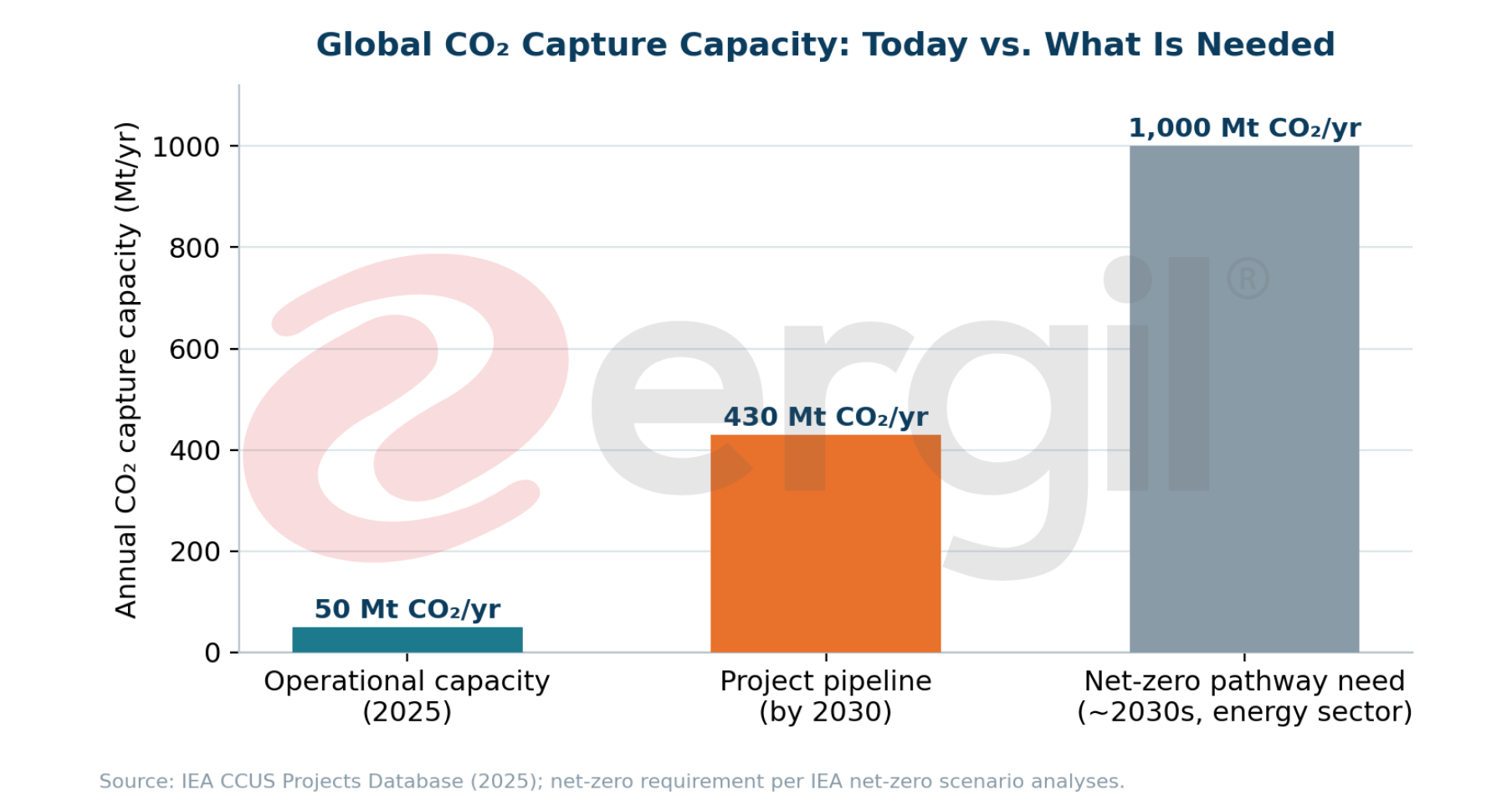
Figure 2. Global CO₂ capture capacity: operational (2025), announced project pipeline (2030), and indicative net-zero requirement. Source: IEA CCUS Projects Database.
How Does a CO₂ Capture System Work?
A CO₂ capture system separates CO₂ from the other components present in a flue gas or process gas stream. The design varies with the source and composition of the gas: CO₂ concentration, gas flow rate, temperature, pressure, and moisture content, as well as SOx, NOx, particulate matter, and other contaminants, are the key parameters considered during process selection.
Once captured, the CO₂ is conditioned according to the requirements of its intended utilization or storage. At this stage, CO₂ purity, water content, pressure, and temperature are controlled. The main stages of the CCS chain are capture, transportation, and storage; in practice, compression, conditioning, and measurement and monitoring also form essential parts of the overall chain.
CO₂ Capture Methods
CO₂ capture processes are broadly classified into three main categories, according to the stage of the combustion process at which capture takes place: post-combustion capture, pre-combustion capture, and oxy-fuel combustion. The table below summarizes how the three routes compare.
| Criterion | Post-Combustion | Pre-Combustion | Oxy-Fuel Combustion |
|---|---|---|---|
| Principle | CO₂ separated from flue gas after fuel combustion | CO₂ removed before combustion, from syngas produced by gasification or reforming | Fuel burned in high-purity oxygen, producing a CO₂-rich flue gas |
| Typical CO₂ concentration | 3–15% (dilute) | 15–60% at elevated pressure | 70–95% after water removal |
| Best suited for | Retrofit of existing power plants, cement, steel, refineries | Hydrogen production, ammonia, IGCC, syngas processes | New-build plants; high-purity CO₂ applications |
| Key advantage | Integrates with existing facilities with minimal process change | High CO₂ partial pressure eases separation | Highly concentrated CO₂ stream simplifies purification |
| Key consideration | Large gas volumes at low CO₂ concentration; regeneration energy | Applicable mainly to gasification/reforming-based processes | Cost and energy demand of the air separation unit |
| Maturity | Commercially proven; most widely deployed for flue gas | Commercially proven in gas processing and hydrogen | Demonstration to early commercial |
Pre-Combustion Capture
Pre-combustion capture separates CO₂ before the fuel is combusted. In gasification or reforming processes, the fuel is converted into a gas mixture containing hydrogen and carbon-bearing compounds. Following the appropriate process steps, CO₂ is separated to produce a hydrogen-rich stream. Because the CO₂ is present at higher pressures in many of these applications, separation is often easier and more energy-efficient. Pre-combustion capture is particularly relevant to hydrogen production and processes involving synthesis gas.
Oxy-Fuel Combustion
In the oxy-fuel process, the fuel is combusted in a high-oxygen environment instead of air. Removing the nitrogen that makes up the bulk of air greatly increases the CO₂ concentration in the resulting flue gas. After water vapour removal and gas conditioning, a highly concentrated CO₂ stream is obtained. The main advantage is this concentrated stream; the main trade-off is the energy demand and cost of oxygen production.
Post-Combustion Capture
Post-combustion capture separates CO₂ from the flue gas generated after fuel combustion. In addition to CO₂, flue gas typically contains large amounts of nitrogen, water vapour, and oxygen, and — depending on the process — SOx, NOx, particulate matter, and other components. Its greatest advantage is retrofitability: post-combustion systems can be integrated into existing facilities with limited disruption to the core process. The challenge is processing large gas volumes at relatively low CO₂ concentrations, which makes equipment sizing and energy consumption central design considerations.
Post-Combustion CO₂ Capture Technologies
The separation technology for a post-combustion system is never selected on CO₂ concentration alone. Gas flow rate, pressure, temperature, impurities, required CO₂ purity, energy consumption, and capital cost are evaluated together.
| Technology | Separation Principle | Typical Application | Key Considerations |
|---|---|---|---|
| Chemical absorption | CO₂ reacts with a reactive solvent (typically amine-based) and is released by heating | Flue gas with low–moderate CO₂ partial pressure; the industry workhorse | Regeneration energy; solvent degradation and corrosion management |
| Physical absorption | CO₂ dissolves in a solvent without chemical reaction; released by pressure reduction | High-pressure, CO₂-rich streams (syngas, natural gas processing) | Less effective at low CO₂ partial pressures |
| Adsorption | CO₂ adheres to solid sorbents (zeolites, activated carbon, MOFs); released by pressure or temperature swing | Medium-scale applications; hydrogen PSA units | Sorbent capacity, cycling stability, bed sizing |
| Membrane separation | Selective permeation of CO₂ through polymeric or inorganic membranes | Natural gas sweetening; compact offshore installations | Trade-off between selectivity, permeability, and achievable purity |
| Cryogenic separation | CO₂ separated by cooling and liquefaction | High-concentration streams; CO₂ liquefaction for transport | High energy demand at low CO₂ concentrations |
Chemical Absorption
Chemical absorption is based on the reaction of CO₂ with a reactive solvent, retaining it in the liquid phase. Amine-based solvents are the most established application. The CO₂-containing gas is introduced into an absorber column and contacted with the solvent; the CO₂-rich solvent is then transferred to a stripper (regeneration) column, where heat releases the CO₂. The regenerated lean solvent returns to the absorber, establishing continuous circulation.
The key advantage of chemical absorption is its ability to remove significant amounts of CO₂ from streams with low to moderate CO₂ partial pressures. The main operating cost is the energy required for solvent regeneration; solvent degradation, solvent losses, corrosion, and the impact of flue gas contaminants on solvent performance must also be addressed during system design.
Amine-Based Capture Systems and Next-Generation Solvents
Amine-based systems play a central role in CO₂ capture, particularly for flue gas streams with low to moderate CO₂ partial pressures. Conventional applications use amines such as monoethanolamine (MEA), diethanolamine (DEA), and methyldiethanolamine (MDEA); in addition, AMP, piperazine-activated solvents, and blended systems combining different amines are in active development.
| Solvent | Type | Typical Strengths | Typical Limitations |
|---|---|---|---|
| MEA (monoethanolamine) | Primary amine | Fast kinetics; proven industrial benchmark; effective at low CO₂ partial pressure | High regeneration energy (~3.6–4.0 GJ/tCO₂); corrosion; oxidative degradation |
| DEA (diethanolamine) | Secondary amine | Lower corrosivity than MEA; established in gas treating | Slower kinetics; moderate regeneration demand |
| MDEA (methyldiethanolamine) | Tertiary amine | Low regeneration energy; high loading capacity; low degradation | Slow CO₂ kinetics — usually requires an activator |
| AMP (2-amino-2-methyl-1-propanol) | Sterically hindered amine | High loading capacity; lower regeneration energy | Slower absorption rate than MEA |
| Piperazine (PZ) blends | Cyclic diamine (activator) | Very fast kinetics; high thermal stability; boosts MDEA/AMP blends | Solubility limits; precipitation management |
| Advanced amine blends | Formulated mixtures | Balanced capacity, kinetics, and energy (~2.5–3.0 GJ/tCO₂); reduced losses | Formulation-specific; requires pilot validation |
A significant share of current solvent development focuses on reducing regeneration energy: capturing CO₂ in the absorber is only half the task — restoring the solvent to a reusable condition determines much of the system’s overall energy consumption. Development of next-generation solvents targets:
Solvent selection should therefore never be based on capture rate alone. Energy requirements, degradation behaviour, compatibility with equipment materials, and long-term operating performance must all be evaluated together.
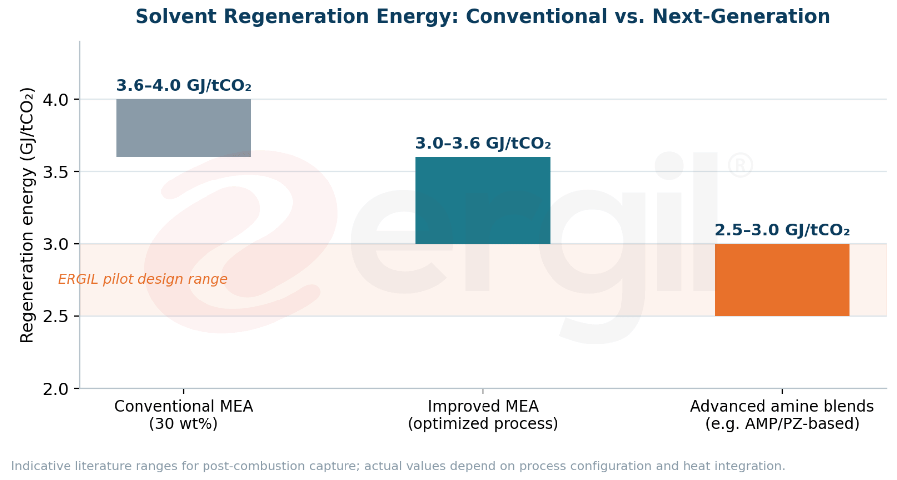
Figure 3. Indicative specific regeneration energy for conventional MEA versus optimized and next-generation amine systems. The ERGIL pilot targets the advanced-blend range of 2.5–3.0 GJ/tCO₂.
Why Is Process Integration Important?
Adding a carbon capture system to an existing facility demands a far more comprehensive engineering approach than installing a new piece of equipment. Flue gas flow rate, temperature, pressure, and composition directly shape the design of the capture unit, while components such as SOx, NOx, particulate matter, and aerosols influence solvent performance and equipment operating conditions. Gas conditioning upstream of the capture unit is therefore often required.
A typical facility-level configuration may be designed as:
Flue Gas → Scrubber → Cooling → Condensation → Filtration / Separation → CO₂ Capture
Following the capture stage, the process continues with:
CO₂ Purification → Dehydration → Compression → Transportation / Storage
The capture system must also be integrated with existing plant utilities — steam, cooling water, electricity, and auxiliary systems. The success of a carbon capture project is consequently never measured by capture rate alone: energy consumption, equipment reliability, maintenance requirements, integration with the existing facility, and operating cost are equally decisive.
Equipment Requirements for Carbon Capture Projects
Carbon capture systems rely on a wide range of process equipment performing distinct functions across the chain. Depending on the facility’s process configuration and the selected capture technology, the system may include:
| Process Stage | Typical Equipment |
|---|---|
| Gas conditioning | Gas scrubbers; gas cooling and conditioning systems; filters and gas separators |
| CO₂ capture | Absorber columns; stripper and regeneration columns; heat exchangers; condensers |
| CO₂ conditioning | CO₂ purification units; dehydration systems; compression systems; pressure control equipment |
| Storage & handling | Storage and buffer tanks; process skids; pressure and vacuum relief equipment |
| Control & safety | Measurement, control, and automation systems |
Equipment selection should never be based on capacity alone. CO₂ operating pressure and temperature, water content, impurities, material compatibility, and expected operating conditions must all be considered. Where CO₂ is present together with water and other contaminants, appropriate material selection and corrosion control are essential for long-term system reliability — a discipline that draws directly on decades of pressure vessel, column, and storage tank engineering.
The ERGIL Carbon Capture Pilot System
ERGIL has developed a modular pilot system based on amine chemical absorption to evaluate CO₂ capture performance under representative industrial process conditions. The system processes gas streams containing 5–15% CO₂ at flow rates of 100–500 Nm³/h, with a target capture efficiency above 95%, depending on operating conditions.
A key feature of the system is its advanced amine blend solvent, selected to balance CO₂ absorption capacity, capture efficiency, and solvent regeneration. Solvent selection considers not only capture performance but also regeneration energy demand, solvent stability, and long-term operating behaviour.
The feed gas is conditioned upstream of the absorber for temperature, moisture, particulate matter, and process-related contaminants. In the absorber, the conditioned gas is contacted counter-currently with the solvent, enabling selective absorption of CO₂. The rich solvent is transferred to the stripper following heat integration; controlled heat input releases the absorbed CO₂, while the regenerated lean solvent is cooled and returned to the absorber, establishing continuous circulation. The CO₂-rich product stream can then be directed to purification, dehydration, and compression stages, depending on the intended application.
Key Specifications
| Parameter | Design / Target Value |
|---|---|
| Flue gas flow rate | 100–500 Nm³/h |
| Inlet CO₂ concentration | 5–15 vol% |
| Operating pressure | 1.1 bar(a) |
| Process temperature range | 40–135 °C |
| Solvent type | Advanced amine blend |
| Target CO₂ capture efficiency | > 95% |
| Target CO₂ product purity | > 99% |
| CO₂ capture capacity | 0.6–5.8 t/day * |
| Specific regeneration energy | 2.5–3.0 GJ/tCO₂ |
| Process configuration | Absorber + stripper / regeneration |
| Operating mode | Continuous, modular pilot system |
| Technology readiness level | TRL 7 — system prototype demonstrated in operational environment |
* Depending on gas flow rate, inlet CO₂ concentration, and operating conditions.
System performance is evaluated against CO₂ capture rate, solvent loading, solvent circulation rate, regeneration energy demand, absorber and stripper operating conditions, CO₂ product purity, solvent stability, and long-term operating performance. The pilot advances process knowledge from laboratory scale toward higher capacities and evaluates operating conditions that closely represent real industrial process environments — generating the process data required for the scale-up of higher-capacity carbon capture systems.
ERGIL Carbon Capture: From Process to Scale
Carbon capture spans a wide range of processes and technologies, so technology readiness should be assessed through the operation of the integrated process as a whole — not through individual equipment performance. ERGIL has developed an integrated, scalable carbon capture platform combining gas conditioning, amine-based CO₂ absorption, solvent regeneration, and downstream CO₂ conditioning within a unified process configuration.
The technology has reached TRL 7, with the integrated pilot system operated under conditions representative of industrial applications. Rather than evaluating the capture unit in isolation, pilot operation considers the interaction between the main process stages: CO₂ capture efficiency, solvent regeneration performance, energy consumption, CO₂ purity, solvent stability, process reliability, and continuous operating performance.
The data generated during pilot operation provide the technical basis for process design, equipment sizing, system integration, performance assessment, and adaptation to different industrial emission sources. From an engineering perspective, ERGIL treats gas conditioning, CO₂ absorption, solvent regeneration, and CO₂ conditioning as interconnected stages of a single process — allowing the system to be configured to the characteristics of each emission source while maintaining a clear pathway toward larger capacities.
Following capture and conditioning, the CO₂ stream can be directed toward utilization or permanent storage. Within a CCUS framework, captured CO₂ may be used in methanol and synthetic fuel production, chemical processes, mineralization, and building materials; where utilization is not technically or economically suitable, the CO₂ is further conditioned for permanent geological storage.
The TRL 7 status provides a validated foundation for the next stage: adapting the platform to higher gas flow rates, different CO₂ concentrations, and specific industrial process conditions. ERGIL’s approach is therefore not limited to CO₂ separation itself — it combines process engineering, equipment design, system integration, and scale-up to deliver modular, application-specific solutions for point-source CO₂ management, from pilot-scale validation to larger industrial installations.