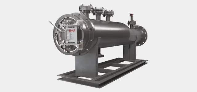
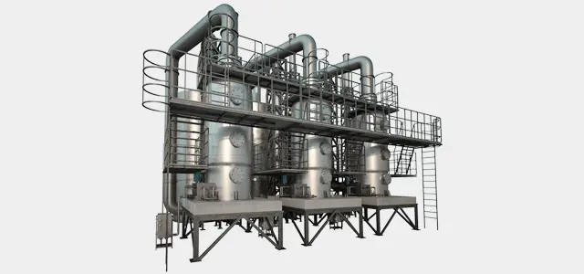
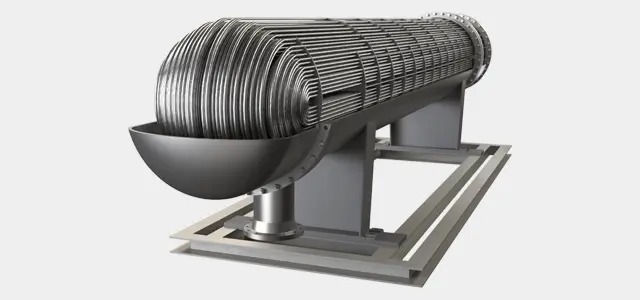
Separator & Filter Vessels
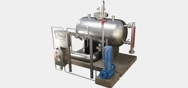
Deaerator Vessels & Feed Water Storage Tanks
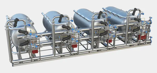
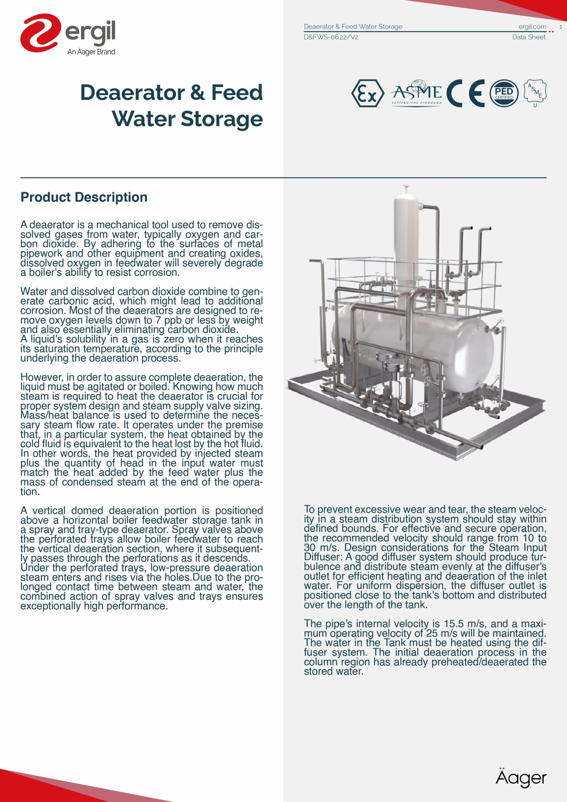
No more operating costs with the latest technology deaerators, also called deaerator tank, Boiler Feedwater Deaerator or deaerator vessels.
With more than 40 years of experience in engineering and manufacturing of Deaerators, An Äager Brand ERGIL is a worldwide active designer, manufacturer, and fabricator company primarily in the oil & gas, chemical and power industry is always ready to take the necessary action to be your reliable partner for your Process Equipment requirements.
The successful removal of oxygen and other dissolved gases from the feedwater to steam generating boilers is possible with this Deaerator from the one-of-its-kind manufacturing facility of An Äager Brand ERGIL. Dissolved oxygen in boiler feedwaters are known to cause corrosion damage by attaching to the walls of metal piping and other metallic equipment, the Deaerator reduces oxygen down to levels of 7 ppb by weight or less.
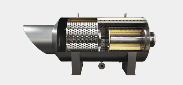
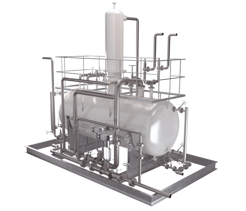
An Äager Brand ERGIL designs, and manufactures two basic types of Dearator- Tray-Type & Spray-Type furnished consisting of Perforated Trays and Vent Condenser with the internal spray distribution system, storage tank, downcomers and pressure equalizing piping between Deaerator and Feed water Storage Tank required, pressure relief doors is furnished in the tray enclosure. Self-draining perforated trays are provided. These Trays is securely fixed in place and deflectors shall be provided to protect trays from direct impingement of steam and feedwater entering Deaerator and Feedwater Storage Tank. Adequate spacing is provided between inlet fluid connections and deaerating components to prevent damage due to transient conditions, flashing or high velocities.
Tray-Type includes a vertical domed Deaeration section mounted on Top of a horizontal cylindrical vessel which serves as the deaerated boiler feed Removes undissolved oxygen Raise the temperature of the feedwater Operating costs can be reduced by recovering flash steam when returned by high-temperature condensate Requires less boiler fuel to convert the feedwater to useable steam water storage tank. Spray-Type consists only of a horizontal cylindrical vessel which serves as both the Deaeration section and the boiler feedwater storage tank. Whether it is refinery application or a power plant, our deaerators are engineered to order as per customer specifications.
- Removes undissolved oxygen
- Raise the temperature of the feedwater
- Operating costs can be reduced by recovering flash steam when returned by high-temperature condensate
- Requires less boiler fuel to convert the feedwater to useable steam
- Provide water storage capacity and the net positive suction head necessary at the boiler feed pump inlet
ERGIL Feedwater Storage Tank is usually designed with a capacity of at least eight (8) minutes of storage of feed water leaving unless specified otherwise. The storage volume is determined as below the normal water level, which should not be greater than 70% of the total storage of the tank.
Feed water is sprayed through spray valves above the perforated trays and then flows downward through the perforations. Low-pressure steam enters below the perforated trays and flows upward through the perforations for allowing it to become quickly heated to saturation. Spraying feed water above the perforated trays increases the surface area of the liquid in contact with the steam, which results in more rapid Oxygen (O2) removal and lower gas concentrations. This process reduces the solubility of all dissolved gases and removes them from the feed water. The liberated gases are then vented from the deaerator.
One (1) 100% Deaerator and Feed-water Storage Tank shall consist of complete workable components and accessories, including the following as a minimum:
- Deaerator, Spray and Tray Type
- Feed-water Storage Tank
- Perforated Trays
- Spray Valves
- Baffles
- Armoured Gauge Glasses
- Safety Valves
- Vent Orifices
- I&C Equipment
- Painting
ERGIL Tray Enclosure is equipped with a Vent Condenser and connected directly to Deaerator Shell. Enclosure Supports with a bolted connection can be welded to an extension piece, but not directly to the pressure boundary. After completion of the assembly, all nuts shall be tightened and tack welded.
All internal structure shall be constructed such that provide limited freedom of movement using of bolted joints to eliminate residual stresses from welding, mitigate thermal stress, promote damping of vibration.
ERGIL Deaerator comes with Down-comers and Equalizers to accommodate drainage of Deaerator Vessel into Feed water Storage Tank at all operating conditions and particularly during transient conditions.
Downcomers and Equalizers are sized so that during transient conditions (except for an instantaneous and momentary condition), condensate flow through downcomers is downward and steam flow through equalizers is upward.
Downcomers and Equalizers are designed according to the differential pressure value between the vessels during transient conditions. In such cases, Equalizers should become flooded and condensate level in Deaerator should not reduce the entering steam flow into the Tank.
Downcomers shall be equipped with deflector hoods to protect the trays against any condensate level rising by diverting steam and condensate flows from Feedwater Storage Tank to Deaerator Vessel and away from trays.
Steam, feedwater, drain, vent and instrument connections are furnished as customer specifications. Connections are sized according to the acceptable inlet and outlet flow velocities of the relevant services and minimize noise levels.
All connection lengths should be designed as per the insulation thickness. We recommend to use Vortex breakers all BFP suction connections and we provide suitable drain connections to drain of Deaerator Vessel and Feedwater Storage Tank completely.
Steam inlet connections are located to provide nearly uniform steam flow over entire tray areas. External or internal steam distribution pipe headers or internal baffles is provided to direct flow to the surface areas of Trays. All steam distributing nozzles shall be arranged on or symmetrically about the midpoint of Deaerator Vessel. Internal sparger pipes shall be located above Feedwater Storage Tank’s water level, for the feedwater pump and feedwater booster pump minimum flow recirculation nozzles. Sparger pipes shall have drilled holes evenly spaced on the bottom 120 degrees of circumference having a total area of at least three (3) times of the nozzle section area.
Pressure and temperature instrument connections shall allow an instrument bridle or standpipe bottom connection a minimum of 150 mm upwards from the bottom of the storage section to prevent foreign materials from blocking the bottom connection, otherwise specified by the client.
Deaerator and Feed water Storage Tank shall be designed and manufactured in accordance with the latest edition, revision or supplement of the applicable standards and codes as indicated but not limited to the following:
- API American Petroleum Institute
- API 510 Pressure Vessel Inspection Code
- In-Service Inspection, Rating, Repair, and Alteration
- ASME American Society of Mechanical Engineers
- ASME BPVC, Section-II Section II, Materials
- ASME BPVC, Section-V Section V, Non-Destructive Examination
- ASME BPVC, Section-VIII, Div. 1 Section VIII, Rules for Construction of Pressure Vessels
- ASME BPVC, Section-IX Section IX, Welding and Brazing Qualifications
- ASME B1.20.1 Pipe Threads, General Purpose
- ASME B16.5 Steel Flanges
- ASME B31.1 Power Piping
- ASME B36.10M Welded and Seamless Wrought Steel Pipe
- ASME PTC 25 Pressure Relief Devices
- Originator ENKA Identification Number: IQ360-000-3SD-MVR0-00001 Rev. B Date 09-02-2018 Lang. EN Sheet 5/11
- ASME PTC 12.3 Performance Test Code on Deaerators
- ASTM American Society for Testing and Materials
- ASTM A105 Carbon Steel Forgings for Piping Applications
- ASTM A106 Seamless Carbon Steel Pipe for High-Temperature Service
- ASTM A179 Seamless Cold Drawn Low Carbon Steel Heat Exchanger and Condenser Tubes
- ASTM A182/182M Forged or Rolled Alloy and Stainless Steel Pipe Flanges, Forged Fittings and Valves and Parts for High-Temperature Service
- ASTM A216/A216M Steel Castings, Carbon, Suitable for Fusion Welding for High-Temperature Service
- ASTM A333/333M Seamless and Welded Steel Pipe for Low-Temperature Service
- ASTM A350/350M Carbon and Low Alloy Steel Forgings, Requiring Notch Toughness Testing for Piping Components
- ASTM A515/A515M Pressure Vessel Plates, Carbon Steel for Intermediate and Higher-Temperature Service
- ASTM A516/A516M Pressure Vessel Plates, Carbon Steel for Moderate and Lower
- 97/23/EC Pressure Equipment Directives (PED)
- 98/37/EC Machinery
- 73/23/EEC Low Voltage Electrical Equipment
- 92/31/EEC Electromagnetic Compatibility
- HEI Heat Exchanger Institute
- HEI 120 Standards and Typical Specifications for Tray Type Deaerator
Deaerator shall be one of several regenerative feedwater heaters using extraction steam from Steam Turbine. Condensate Pumps shall supply condensate water to Deaerator from the Condenser Hotwell.
Deaerator and Feedwater Storage Tank shall be capable of continuously furnishing deaerated water at storage tank outlet at any rate from 10 to 100% of steady-state maximum flow with a residual Oxygen (O2) content not exceeding 7 ppb and reducing free Carbon Dioxide (CO2) content to zero over entire load range and heating deaerated water to saturation temperature corresponding to steam pressure maintained in shell.
Vent condenser shall be capable of preventing undue loss of steam through vent connection under all conditions of operation. Steam losses to the Vent Condenser shall not exceed 0.5% of the total steam required to heat the condensate.
Feedwater Tank is designed in accordance with ASME Boiler and Pressure Vessel Code (BPVC) Section VIII Division 1, HEI Standards (Section 5.2), design conditions are given in the Data Sheet for Deaerator and Feed water Storage Tank and Site-Specific Conditions (i.e. ambient conditions, wind loads, seismology …etc) are given in General Project Requirements Specification. Both Deaerator and Feedwater Storage Tank shall have ASME Code Stamp.
Deaerator and Feedwater Storage Tank shall be designed for STG valves wide open (V.W.O) load corresponding to peak Combined Cycle Plant output and also capable of continuous and safe operation over the full range of steam and water temperatures and pressures.
Heater supports shall be suitable to withstand forces and moments imposed on heater nozzles by the Owner’s attached piping.
Deaerator and also Feedwater Storage Tank shells are designed for working pressures from full vacuum (FV) to the design pressure as per customer requirement.
Pipes and nozzles shall be designed to distribute condensate over trays for concurrent full internal vacuum and full exterior deaerator pressure to withstand pressure resulting from liquid flashing in a pipe before nozzles or spray holes, opening control valve that supplies condensate to empty spray pipe, or filling the empty system. Design trays safely withstand impact energy of condensate on trays resulting from the above-described pressure peaks.
Deaerator and Feedwater Storage Tank are designed to minimize noise and vibration at all flow rates up to and including maximum capacity, during rapid load changes, and for entering feedwater temperature ranging from steady state to the normal condenser hot well temperature.
All components having safe working stresses which are not exceeded during all conditions of operation (i.e. startup, steady state at any load from zero to full load, transient conditions) and forces caused by flashing of liquid in the storage tank. Trays, tray enclosure, and support members shall be designed to withstand maximum pressure differential across the trays and tray enclosure during any condition of operation. Transient conditions which occur upon sudden load rejection, assuming that all steam flow has stopped while condensate continues to enter the deaerator at the maximum flow rate for transient or condensate control valve failed wide open, resulting in pressure differential across the tray enclosure.
Do you have Questions?
Want to know more? Check out our catalog for a complete overview of our offerings. With our catalog, you’ll have access to all the technical details you need to make an informed decision about our Deaerator Vessels & Feed Water Storage Tanks.
Do you need a quick quotation?


Request A Quote
Do you need a quick quotation? Fill out the below form and expect our reply soon


