

ATMOSPHERIC SYSTEMS
ATMOSPHERIC VENTING & RELIEF DISPOSAL SYSTEMS
Vent Stack · Knock-Out Drum · Liquid Seal Drum
Complete Engineered Solutions for Safe Atmospheric Discharge
ENGINEERING · MANUFACTURING · COMMISSIONING
01 · WHY IT MATTERS
ATMOSPHERIC VENTING & RELIEF SYSTEMS
The final engineered barrier between overpressure and catastrophic failure
Every hydrocarbon processing facility operates under carefully controlled pressure boundaries. When those boundaries are challenged — by blocked outlets, runaway reactions, fire exposure, utility failure, or operator error — the plant’s pressure relief philosophy must respond reliably and without compromise.
Atmospheric venting and relief disposal systems constitute the terminal stage of that philosophy. They receive gas and vapor streams discharged from pressure relief valves, rupture discs, emergency depressurization valves, and process blowdowns, then route them safely to atmosphere — preventing liquid carryover onto grade, eliminating reverse flow and flashback risk, and dispersing vapor above the breathing zone.
Failure to engineer this system correctly results in liquid rain-out from vent stacks, back-ignition into relief headers, air ingress into flammable gas systems, or inadequate dispersion leading to vapor cloud formation at grade level. The consequences range from equipment damage to major loss-of-life events.
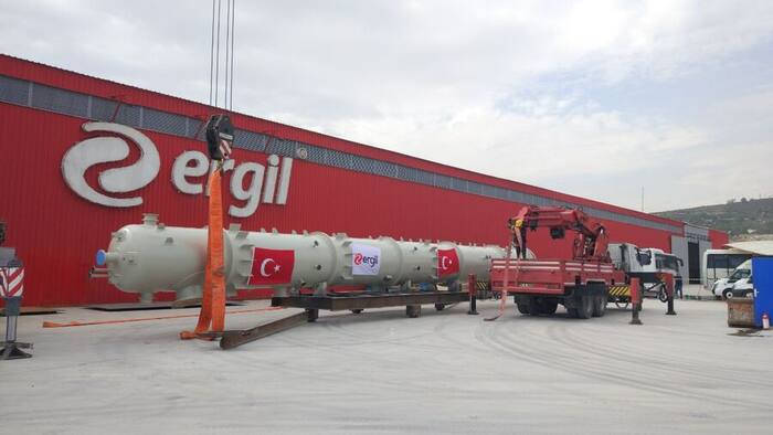
ERGIL Mersin manufacturing facility — 60,000 m² in-house fabrication capability
INTEGRATED SYSTEM — PROCESS FLOW SEQUENCE
RELIEF SOURCES
PRVs · BDVs · RDs ▶ RELIEF HEADER
Collection piping ▶ KNOCK-OUT DRUM
Liquid separation ▶ SEAL DRUM
Hydraulic seal ▶ VENT STACK
Atmospheric discharge ▶ SAFE DISCHARGE
Above grade
INDUSTRIES SERVED
Refining Petrochemical Oil & Gas LNG Chemical Fertilizer Hydrogen Water Treatment Tank Farms
02 · COMPONENT · FIRST IN CLASS
COLD VENT STACK
Atmospheric dispersion of relief gases at safe elevation above occupied grade and ignition sources
Function: The vent stack elevates the point of atmospheric discharge to a height sufficient to ensure safe vapor dispersion per API 521 / EN 13237 requirements. It is the terminal point of the cold vent system, handling gases that have been stripped of entrained liquids by the upstream KOD and Seal Drum.
Operating Principle: Gas enters the stack from the Seal Drum outlet at near-atmospheric pressure. Stack diameter is sized for a maximum exit velocity (typically 0.5 Mach for sonic-tip designs) to prevent downdraft re-entrainment into the breathing zone. Self-supporting stacks are designed for combined wind, seismic, thermal, and vortex-shedding loads.
Structural Design: For stacks with slenderness ratio H/D exceeding 25, vortex-induced vibration (VIV) analysis is mandatory. ERGIL performs Strouhal frequency calculations and specifies aerodynamic spoilers or tuned mass dampers where required. Foundation loads are reported for civil design.
STACK CONFIGURATIONS
MATERIALS AVAILABLE
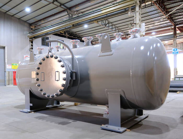
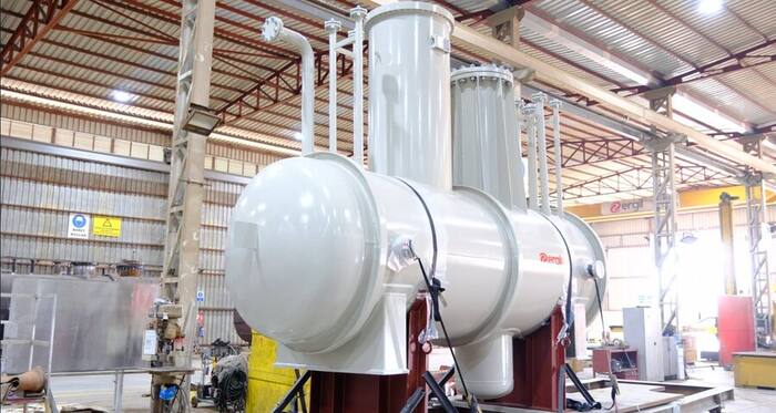
ERGIL cold vent stack and liquid seal drum — integrated skid, factory acceptance test
03 · COMPONENT · FIRST STAGE SEPARATION
KNOCK-OUT DRUM
Gravity and inertial separation of entrained liquids from relief gas streams prior to atmospheric discharge
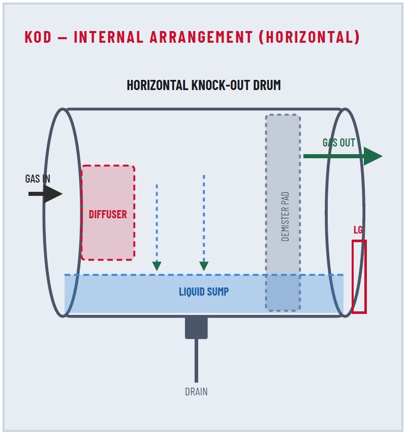
KOD — Internal Arrangement (Horizontal): Diffuser · Demister Pad · Liquid Sump · Gas In / Gas Out · LG · Drain
Purpose: The Knock-Out Drum is the first stage of liquid separation in the cold vent system. Relief gas from the plant header frequently contains entrained liquid — from condensation in headers, carry-over from process upsets, or direct liquid relief events. If not removed, this liquid will discharge from the vent stack as liquid rain-out, creating a fire hazard and personnel safety risk at grade.
Internal Components: The inlet diffuser dissipates the momentum of the incoming stream, reducing internal velocity below the critical droplet re-entrainment velocity. Larger droplets fall by gravity into the sump. A demister pad (100–150 mm wire mesh or vane type) captures sub-micron mist via inertial impaction and coalescence. The sump provides liquid hold-up volume for accumulated condensate pending controlled drain-down.
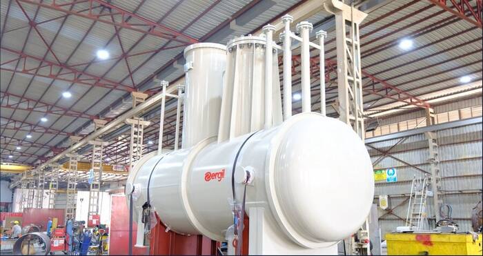
ERGIL horizontal Knock-Out Drums — ready for shipment from Mersin facility
STANDARD NOZZLE SCHEDULE
| TAG | SERVICE | TYPICAL SIZE |
|---|---|---|
| N1 | Gas inlet from header | DN 200–600 |
| N2 | Gas outlet to seal drum | DN 200–600 |
| N3 | Liquid drain (closed drain) | DN 50–80 |
| N4 | Pressure gauge / transmitter | DN 25 |
| N5 | Level gauge / transmitter | DN 50 |
| N6 | Manway (inspection access) | DN 500–600 |
04 · COMPONENT · HYDRAULIC SAFETY BARRIER
LIQUID SEAL DRUM
Hydraulic sealing against air ingress, flashback, and reverse flow — the pressure break between the relief system and atmosphere
Hydraulic Sealing Principle: The Seal Drum creates a positive liquid seal between the relief header and the vent stack. The inlet dip pipe terminates below the liquid surface. Gas must overcome the hydrostatic head H of the liquid column before bubbling through to the vent stack — setting a controlled back-pressure on the relief header and preventing atmospheric air from migrating into the flammable gas system.
Flashback & Reverse Flow Protection: Under transient vacuum conditions in the header, the liquid seal prevents air ingress that could form an explosive mixture in the relief piping. The hydraulic barrier responds instantaneously without mechanical moving parts, providing inherently fail-safe protection independent of instrument air, power supply, or operator action.
Final Liquid Separation: Residual liquid mist passing through the KOD impinges on the internal baffle above the liquid surface and coalesces. The outlet nozzle to the vent stack is positioned well above the liquid level, ensuring gas-only flow under all normal and relief conditions.
KEY DESIGN ELEMENTS
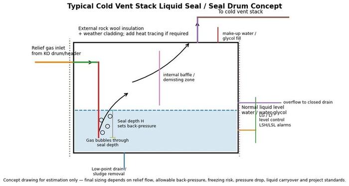
ERGIL cold vent stack liquid seal / seal drum concept drawing
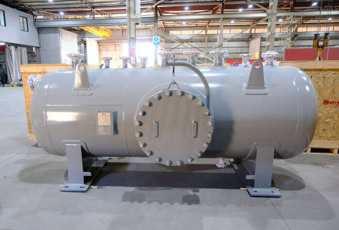
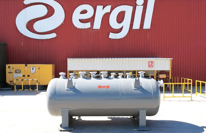
ERGIL liquid seal drums — large-bore horizontal design, Mersin facility
05 · ENGINEERING BASIS
DESIGN PHILOSOPHY & KEY PARAMETERS
Every ERGIL system is engineered to site-specific process conditions, design codes, and environmental criteria
PROCESS DESIGN PARAMETERS
| Parameter | Typical Range | Design Impact |
|---|---|---|
| Normal operating flow | 1 – 500,000 Nm³/h | KOD & stack sizing |
| Peak relief flow | Up to 2,000,000 Nm³/h | Stack tip velocity |
| Gas temperature | −196 °C to +650 °C | Material selection |
| Operating pressure | Near-atmospheric | Wall thickness (FV) |
| Molecular weight | 2 – 120 g/mol | Dispersion / buoyancy |
| H₂S content | 0 – 100 mol% | NACE MR0175 |
| Liquid carryover | 0.1 – 5,000 kg/h | KOD sump volume |
STRUCTURAL & ENVIRONMENTAL LOADS
RELIEF SCENARIOS CONSIDERED
| Scenario | API 521 § |
|---|---|
| Fire case (pool fire / jet fire) | 5.15.1.2 |
| Blocked outlet | 5.15.1.1 |
| Cooling water failure | 5.15.1.4 |
| Control valve failure open | 5.15.1.5 |
| Reflux failure | 5.15.1.6 |
| Utility failure (power/steam) | 5.15.1.9 |
| Emergency depressurization | 5.20 |
MATERIAL SELECTION GUIDE
| Service Condition | Recommended Material |
|---|---|
| Standard hydrocarbon | SA-516 Gr. 70 / P265GH |
| Low-temperature (≤ −29 °C) | SA-516 Gr. 70 + PWHT / P355NL |
| Cryogenic (≤ −46 °C) | 3.5% Ni / 9% Ni / 304L SS |
| Sour service (H₂S, NACE) | HIC-tested plate; NACE MR0175 |
| Acid / high-chloride | 316L SS / 2205 Duplex SS |
| High-temperature (>400 °C) | 1.25Cr–0.5Mo / 310 SS |
06 · SPECIFICATIONS
TECHNICAL DATA SHEETS
Indicative design parameters — all values are project-specific and subject to ERGIL engineering review and client approval
VENT STACK — TECHNICAL DATA SHEET (INDICATIVE)
| Design Parameter | Standard Range | Code / Standard |
|---|---|---|
| Stack height | 6 – 120 m (shipped in sections above 40 m) | API 521 §5.6 |
| Stack diameter (ID) | DN 150 – DN 2,000 | Sized for exit Mach ≤ 0.5 |
| Design pressure | Full vacuum (FV) / +0.5 barg | ASME Sec. VIII Div. 1 |
| Design temperature | −46 °C to +450 °C | Per process data |
| Base material | CS / 304L SS / 316L SS / Duplex 2205 | Per process & site |
| Corrosion allowance | 1.5 – 3.0 mm (CS service) | Project specification |
| Wind design code | ASCE 7-22 / EN 1991-1-4 | Site-specific wind zone |
| Surface preparation | Sa 2.5 (Near-white blast) | SSPC-SP10 / ISO 8501-1 |
| Coating system | 3-coat epoxy/polyurethane, min. 250 µm DFT | Project painting spec. |
| NDE requirements | 100% RT/UT on all circumferential butt welds | ASME B31.3 / PED |
KNOCK-OUT DRUM — TDS
| Parameter | Range / Value |
|---|---|
| Orientation | Horizontal or Vertical |
| Shell ID | 600 – 4,000 mm |
| T-T length | 1,000 – 20,000 mm |
| Design pressure | FV / +1.0 barg |
| Design temperature | −46 / +400 °C |
| Demister pad | 100 mm wire mesh, SS wire |
| Liquid holdup vol. | 10–60 min at design flow |
| Nozzle rating | ASME B16.5 / EN 1092-1 |
| Inspection code | ASME Sec. VIII Div. 1 |
| Stamp / marking | ASME U stamp / PED CE |
| Hydro test pressure | 1.3 × MAWP (per ASME) |
LIQUID SEAL DRUM — TDS
| Parameter | Range / Value |
|---|---|
| Orientation | Horizontal (standard) |
| Shell ID | 600 – 3,500 mm |
| Seal depth (H) | 250 – 600 mm WC |
| Seal liquid | Water / MEG-water mixture |
| Design pressure | FV / +0.5 barg |
| Design temperature | −46 °C / +200 °C |
| Level instruments | LG + LT (HART) + LSH/LSL |
| Make-up connection | DN 25–50 (auto or manual) |
| Insulation | Rock wool 50–100 mm |
| Heat tracing | Electric / steam (optional) |
| Inspection code | ASME Sec. VIII Div. 1 |
07 · COMPLETE PACKAGE
OPTIONAL SCOPE & ACCESSORIES
ERGIL supplies complete, ready-to-install packages — from bare equipment to fully skid-mounted, instrumented, and tested systems
STRUCTURAL ACCESSORIES
INSTRUMENTATION PACKAGE
AVIATION OBSTRUCTION LIGHTING
THERMAL MANAGEMENT
SKID-MOUNTED PACKAGES
ERGIL offers fully integrated skid-mounted packages combining the Knock-Out Drum and Seal Drum on a single structural steel baseframe. Benefits include reduced civil scope, pre-tested interconnecting piping, factory acceptance testing (FAT) of the combined unit, and single-lift installation.
MONITORING & CONDITION SYSTEMS
08 · MARKET COVERAGE
INDUSTRIES & APPLICATIONS
ERGIL atmospheric venting systems operate across the full spectrum of hydrocarbon and chemical processing industries
OIL & GAS PRODUCTION
Wellhead and production platform cold vent stacks. Slug catcher KODs. Process separator atmospheric relief. ESD depressurization systems. Offshore wind & seismic design. ATEX Zone 1 instrumentation.
REFINING
Crude distillation unit relief header systems. Vacuum unit barometric condenser stacks. Catalytic cracker relief management. Hydrocracker/hydrotreater H₂ vent stacks. NACE MR0175 sour service KODs.
PETROCHEMICAL
Ethylene/propylene cracker vent stacks. Polymerization reactor relief systems. Aromatic plant (BTX) cold vent systems. Butadiene and styrene relief disposal. Cryogenic service KODs to −196 °C.
LNG & GAS PROCESSING
LNG terminal cold vent stacks. Cryogenic seal drums with MEG freeze protection. Gas sweetening unit relief headers. Amine regenerator vent stacks. BOG compressor relief disposal.
CHEMICAL PLANTS
Chlor-alkali H₂/Cl₂ vent systems. Ammonia and urea plant relief management. Specialty chemical seal drums in exotic alloys. Reactive chemistry emergency vent systems.
FERTILIZER
Ammonia synthesis loop vent stacks. Urea reactor pressure relief systems. Granulation plant KODs. Nitric acid tail gas seal drums. CO₂ recovery unit relief disposal.
HYDROGEN & ENERGY
Green hydrogen electrolyzer vent stacks. SMR/ATR reformer relief systems. Hydrogen storage facility cold vents. Fuel cell plant safety relief disposal. Power-to-X process venting systems.
WATER TREATMENT
Biogas and digester gas vent stacks. Wastewater H₂S relief systems. Anaerobic digestion plant safety venting. Desalination facility relief management. Chemical dosing area vent systems.
TANK FARMS & TERMINALS
Bulk liquid terminal tank vent stacks. Loading arm vapour recovery backup. Fuel storage pressure management. Blending facility relief header systems. Import/export terminal ESD vent systems.
09 · COMPETITIVE ADVANTAGE
THE ERGIL DIFFERENCE
A single-source engineered solution — from process datasheet to commissioned and handed-over system
ASME U ASME U2 EN AD 2000 PED/CE ISO 9001 ATEX IECEx
FULL PROJECT EXECUTION — STAGE BY STAGE
01 Inquiry Review & Process Engineering
Datasheet review, sizing basis, code selection, hazard identification
02 Detail Engineering
Mechanical calculations, GA drawings, material specs, nozzle schedules
03 Document Submission & Client Approval
ITP, GA drawings, datasheet and specification approval
04 Fabrication & Third-Party Inspection
Witnessed by client and/or TÜV, BV, LRQA, DNV, SGS
05 Testing & Certification
Hydrostatic test; NDT; painting; code stamping; name plate
06 Packaging & Logistics
Sea-worthy crating; export documentation; multi-modal shipping
07 Site Supervision & Commissioning Support
Resident engineer; pre-commissioning; seal filling; handover documentation